BASICS of a Membrane Switch
Anatomy of a Membrane Switch
A membrane switch is an electrical switch for turning a circuit on and off. It differs from a mechanical switch, which is usually made of metal and plastic parts. A membrane switch is a circuit printed on a flexible material like Polyester or Polycarbonate.The ASTM defines a membrane switch as a momentary switch device in which at least one contact is on, or made of, a flexible substrate.
Construction Layers
A Membrane Switch can be as simple as a two layer construction or a multi-layered complicated assembly. Regardless, as a momentary switch, must contain Membrane Layer and Static Layer.All other layers required for decoration, backlighting, adhesive, tactile response and rigid support are all optional.
A short explanation and example of each layer:
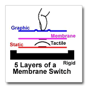
1. Graphic Layer
Decoration of a membrane switch is conventionally accomplished with thin, screen printed, polyester or polycarbonate. Elastomer is also a method of decorating a switch assembly and an attractive and functional alternative especially when a three dimensional look and feel is desired.2. Membrane Layer
As discussed above the Membrane Layer is thin & pliable and carries at least one of the poles of the switch or carries a conductive shorting pad. This is a required layer. Materials used are: Polyester, Metal Dome, Elastomer, Polyimide.3. Tactile Layer
There are several ways to create a tactile response, some are a result of forming another layer. For example a dome embossed polyester overlay means the graphic layer is also the tactile layer. If a poly dome is formed in the membrane layer means it doubles as the tactile layer. Obviously if the tactile layer is absent, you have a non-tactile membrane switch. Options for Tactile Layers are Metal Dome, Polyester Dome, Dome Emboss in the Graphic Layer, Elastomer.4. Static Layer
The Static Layer is rigidly supported and carries at least one of the poles of the switch or carries a conductive shorting pad. The Static Layer is a required component of a membrane switch. It is constructed from materials such as Polyester, transparent conductor, ITO, Polyimide and Printed Circuit Board.5. Rigid Layer
If the static layer is made from a flexible material it must be laminated to a rigid material. Many membrane switches are purchased without a rigid backer and the static layer does not become truly static until it is attached permanently to the instrument housing. Example materials: Aluminum, Steel, Plastic, Glass, Fiberglass.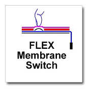
Membrane Switch Types
There are FIVE basic types of Membrane Switches.- Flex membrane switch
- Transparent membrane switch
- Elastomer Membrane Switches
- PCB Membrane Switch
- Packaged Membrane Switch
1. Flex Membrane
Of the five categories of membrane switches the most common is the Flex Membrane Design.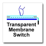
- This construction incorporates the conventional thin, flexible, polyester or polyimide circuit layer. This allows efficient manufacturing producing many circuit images rapidly using screen printing or etching processes. •
- Even though the entire switch package is made from flexible materials there are many options available.
- The keys can be made to provide either a tactile sensation or no sensation at all (like on most microwave ovens). Metal domes or formed polyester domes are used to provide a tactile response to the keys.
- Backlighting can be achieved as well by laminating or inserting discrete LEDs or illuminating large areas using fiber optics or electroluminescents.
- Decoration can be a conventional polyester or polycarbonate screen printed layer or elastomer or plastic keys to satisfy a more 3D approach to the graphic layer.
2. Transparent Membrane
Most of the time you will see the Transparent Membrane Switch referred to as a touch screen.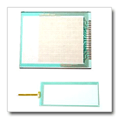
- Sometimes called a Resistive Touch Screen, as opposed to Capacitive, Acoustic Wave, Infra red, or Force Sensing. The membrane, or flexing layer, is thin, transparent polyester, and conductively coated.
- When pressed the transparent conductive coating makes ohmic (or resistive) contact with another transparent conductor, the static layer.
- The Static layer can be made of the same material as the membrane layer or a clear rigid material that is also conductively coated.
- Two types of transparent membranes are available; Analog & Digital. The Transparent membrane can also be incorporated into the display window of a Flex or PCB Membrane Switch.
- A very versatile option for applications where key function or key locations change often.
3. Elastomer Membrane
Elastomer Membrane Switches are used everyday in remote controls and cell phones.
- If a silicone rubber keypad is used as the graphic layer and/or membrane layer it would fall in this category.
- One way to distinguish between two different methods of creating a tactile response is whether or not the tactile layer is caused by the elastomer itself or from something beneath the rubber layer.
- If the elastomer is both the membrane layer and the tactile layer means the tactile response is internal to the keypad.
- If the elastomer is the graphic layer only, and the tactile response is from metal dome, polyester dome or packaged membrane then it can be refereed to externally tactile keypad.
- Elastomer membrane switches can have a flex static layer or rigid static layer (PCB). The simplest elastomer membrane switch is made with two layers using a decorative elastomer internally tactile over a PCB.
4. PCB Membrane
The PCB Membrane Switch design tends to be the most versatile of the five membrane switch categories.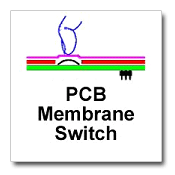
- The PCB is the static layer but also doubles as the rigid layer thus making a very simple assembly.
- The PCB can also be used to for soldered components allowing the side opposite of the graphic layer to used for mounting displays, backlighting, or interface electronics. Keys can be made to provide either a tactile sensation or no sensation at all (like on most microwave ovens). Metal domes,formed polyester domes or elastomer snap can be used to provide a tactile response to the keys.
- Backlighting can be achieved as well by laminating or inserting discrete LEDs or illuminating large areas using fiber optics or electroluminescents.
- Decoration can be a conventional polyester or polycarbonate screen printed layer or elastomer or plastic keys to satisfy a more 3D approach to the graphic layer.
5. Packaged Membrane
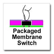 A Packaged Membrane Switch is a purchased component. By itself satisfies the membrane
switch definition by having both a membrane layer and static layer internal to the
switch enclosure.
Most packaged membrane switches have a tactile response created by a collapsing elastomer key, polyester or metal suspended internally in the switch package.
Packaged membrane switches have two pins for soldering to a PCB. The soldering connects both poles of the switch to the PCB but also provides mechanical stability.
A multiple switch array is created by soldering many of these packaged membrane switches to a PCB in a predetermined arrangement.
Then, by decorating with a screen printed or elastomer graphic layer will present to the user what appears and feels like a conventional flex membrane switch.
Packaged membrane switches are popular for those applications where key legends are changing often.
Packaged switches can also be replaced if needed which in some applications can be easier than replacing the entire membrane switch assembly.
Overlay Embossing Design Options
Reliance offers various embossing options. The following designs are examples of what can be accomplished. A design can have a combination of options on one overlay.
Type |
Shape |
Comments |
| Pillow |

|
The pillow emboss allows the membrane switch to be a thinner construction when tactile feedback is required. The pillow will rest over a metal or polyester dome and provide positive tactile feedback. |
| Rim |

|
The rim emboss is utilized on membrane switches (with or without tactile feedback). This design allows the user to locate the key easier. |
| Dual |

|
The dual emboss is used in special designs, such as In Mold Decorating (IMD). This feature allows the overlay to have an emboss as well as a deboss in the same key. |
| LED or Brail |

|
The LED window emboss is utilized on membrane designs with LED's incorporated into the package. This methodology is an effective way to design a thinner switch, versus a flat membrane with LED's and provides a wider viewing angle than a typical flat overlay window. |


